Adding a third interrupt source to this board is where I stopped trusting the priority numbers in our project. GPIO, ADC and FlexPWM all reach the CPU through the same NVIC, all get a 4-bit priority, and all look interchangeable in the Config Tool.
They are not. FreeRTOS draws a hard line through that priority range, and which side of it an ISR lands on decides whether it is allowed to call a FreeRTOS API at all. Get it wrong and nothing fails immediately — you get an assert under load, or worse, silent scheduler corruption months later.
So the useful exercise is not “how do I set up a GPIO interrupt”. It is “what is actually in my NVIC table, and is every entry on the right side of the line”.
In this article I show the configuration pattern the three sources share, the two places they genuinely differ, and how to audit a real NVIC table against the FreeRTOS barrier.
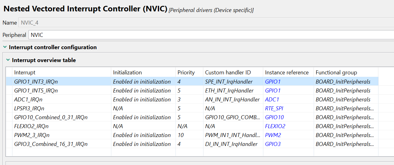
A real NVIC table from this project. Three entries sit at priority 3 and 4 — above the FreeRTOS syscall barrier. That is the audit.
TL;DR
configLIBRARY_MAX_SYSCALL_INTERRUPT_PRIORITY numerically, you may call *FromISR APIs. Below
it, you may not — ever.The barrier
The RT1062 routes all peripheral interrupts through the Cortex-M7 NVIC. Priority is a 4-bit field, 0 = highest, values 0–15. FreeRTOS reserves the top band for its own kernel tick and scheduler:
configLIBRARY_MAX_SYSCALL_INTERRUPT_PRIORITY = 5

  priority 0-4   above the barrier  -> hard-RT only. Calling ANY FreeRTOS API
                                       from here is undefined behaviour.
  priority 5-15  below the barrier  -> xTaskNotifyFromISR(), xQueueSendFromISR()
                                       and friends are safe.
Note the inversion that trips people up: numerically lower means higher priority means less allowed. An ISR at priority 3 is more urgent and more restricted than one at 10.
Audit your own table before reading further
In the NVIC table above, ADC1_IRQn is at priority 3, and GPIO1_INT3_IRQn and
GPIO3_Combined_16_31_IRQn are at 4. All three are above the barrier. Those handlers —
AN_IN_INT_IrqHandler, SPE_INT_IrqHandler, DI_IN_INT_IrqHandler — must not call any
FreeRTOS API, not xTaskNotifyFromISR, not xQueueSendFromISR, nothing. If they need to hand
data to a task, it has to be a volatile variable plus a memory barrier, picked up by a
lower-priority ISR or a polling task.
PWM2_3_IRQn at priority 10 is comfortably below the barrier and can post freely. That is the
one this project’s context-switching walkthrough
traces end to end.
Go read your own NVIC table before you add the next interrupt. The Config Tool will not warn you.
The pattern all three share
Every RT1062 peripheral pin goes through two layers before an interrupt can fire:
- IOMUXC — selects the alternate function and the electrical pad settings. The pad fields are worth understanding properly; I wrote them up in pin config: pull/keeper, drive strength and slew rate.
- Peripheral clock gate — must be enabled before touching any peripheral register.
The Config Tool generates both into pins.c and clock_config.c. By hand:
/* GPIO1_IO04 as a GPIO input with interrupt */
IOMUXC_SetPinMux(IOMUXC_GPIO_AD_B0_04_GPIO1_IO04, 0U);
IOMUXC_SetPinConfig(IOMUXC_GPIO_AD_B0_04_GPIO1_IO04,
    IOMUXC_SW_PAD_CTL_PAD_HYS(1)   |   /* hysteresis — mechanical input   */
    IOMUXC_SW_PAD_CTL_PAD_PUS(1)   |   /* 47k pull-up                     */
    IOMUXC_SW_PAD_CTL_PAD_PUE(1)   |
    IOMUXC_SW_PAD_CTL_PAD_PKE(1));

The same settings as generated output. Hysteresis is enabled on the digital inputs and disabled on the analogue ones — correct, and worth checking rather than assuming.
From there the sequence is identical for all three peripherals:
- Enable the peripheral clock.
- Configure the peripheral.
- Clear the pending flag — before enabling, or you take a spurious first interrupt.
- Enable the interrupt inside the peripheral.
- Set the NVIC priority — before
EnableIRQ(). EnableIRQ().
GPIO
Interrupt detection lives inside the GPIO block (GPIO1–GPIO9). Each pin can be configured for rising edge, falling edge, both edges, high level or low level.
CLOCK_EnableClock(kCLOCK_Gpio1);

gpio_pin_config_t cfg = { kGPIO_DigitalInput, 0, kGPIO_IntRisingEdge };
GPIO_PinInit(GPIO1, 4U, &cfg);

GPIO_ClearPinsInterruptFlags(GPIO1, 1U << 4U);   /* before enabling */
GPIO_EnableInterrupts(GPIO1, 1U << 4U);

NVIC_SetPriority(GPIO1_Combined_0_15_IRQn, 6U);  /* >= MAX_SYSCALL */
EnableIRQ(GPIO1_Combined_0_15_IRQn);
void GPIO1_Combined_0_15_IRQHandler(void)
{
    uint32_t flags = GPIO_GetPinsInterruptFlags(GPIO1);

    if (flags & (1U << 4U))
    {
        GPIO_ClearPinsInterruptFlags(GPIO1, 1U << 4U);

        BaseType_t xHigherPriorityTaskWoken = pdFALSE;
        xTaskNotifyFromISR(xTargetTask, 0, eNoAction, &xHigherPriorityTaskWoken);
        portYIELD_FROM_ISR(xHigherPriorityTaskWoken);
    }
}
One vector, sixteen pins
GPIO1 pins 0–15 all share GPIO1_Combined_0_15_IRQn. The handler must read the flag register and
work out which pin fired — and clear only that pin’s flag.
Separately: GPIO1 and GPIO6 reach the same physical pads. Standard GPIO (1–5) goes through the AHB bus; fast GPIO (6–9) maps to the TCM crossbar. If you need sub-microsecond response, use the fast alias.
ADC
The RT1062 has two 12-bit SAR ADCs. A conversion-complete interrupt fires when the result register is ready, and the flag clears when you read the result — no explicit clear.
CLOCK_EnableClock(kCLOCK_Adc1);

adc_config_t adcCfg;
ADC_GetDefaultConfig(&adcCfg);
adcCfg.resolution = kADC_Resolution12Bit;
ADC_Init(ADC1, &adcCfg);

ADC_DoAutoCalibration(ADC1);          /* mandatory after power-on reset */

adc_channel_config_t chCfg = {
    .channelNumber                        = 0U,   /* ADC1_IN0 */
    .enableInterruptOnConversionCompleted = true,
};
ADC_SetChannelConfig(ADC1, 0U, &chCfg);  /* also kicks off the first conversion */

NVIC_SetPriority(ADC1_IRQn, 6U);
EnableIRQ(ADC1_IRQn);
void ADC1_IRQHandler(void)
{
    /* Reading the result register clears the interrupt flag. */
    uint32_t result = ADC_GetChannelConversionValue(ADC1, 0U);

    BaseType_t xHigherPriorityTaskWoken = pdFALSE;
    xQueueSendFromISR(xAdcQueue, &result, &xHigherPriorityTaskWoken);
    portYIELD_FROM_ISR(xHigherPriorityTaskWoken);
}
Two things to watch. ADC_DoAutoCalibration() is not optional — skip it and your readings carry
an offset you will spend an afternoon chasing. And in continuous-conversion mode the ISR fires at
the sample rate: a 16-cycle conversion on a 1 MHz ADC clock is roughly a 62 kHz interrupt rate,
which will starve the scheduler. Above a few kHz, use DMA.
Note that the ISR above assumes ADC1_IRQn sits below the barrier. In the real table at the top
of this article it is at priority 3, so that version of the handler would be wrong for this
project.
FlexPWM
Four modules (PWM1–PWM4), each with four submodules (SM0–SM3). Each submodule has its own compare registers and can interrupt on compare match, reload, or a hardware fault input.
CLOCK_EnableClock(kCLOCK_Pwm1);

pwm_config_t pwmCfg;
PWM_GetDefaultConfig(&pwmCfg);
pwmCfg.reloadLogic = kPWM_ReloadPwmFullCycle;
pwmCfg.clockSource = kPWM_BusClock;
pwmCfg.prescale    = kPWM_Prescale_Divide_4;
PWM_Init(PWM1, kPWM_Module_0, &pwmCfg);

pwm_signal_param_t signal = {
    .pwmChannel       = kPWM_PwmA,
    .dutyCyclePercent = 50U,
    .level            = kPWM_HighTrue,
};
PWM_SetupPwm(PWM1, kPWM_Module_0, &signal, 1U, kPWM_EdgeAligned,
             20000U, CLOCK_GetFreq(kCLOCK_IpgClk));

PWM_EnableInterrupts(PWM1, kPWM_Module_0, kPWM_CompareVal0InterruptEnable);

NVIC_SetPriority(PWM1_0_IRQn, 6U);
EnableIRQ(PWM1_0_IRQn);

PWM_StartTimer(PWM1, kPWM_Control_Module_0);
void PWM1_0_IRQHandler(void)
{
    uint16_t flags = PWM_GetStatusFlags(PWM1, kPWM_Module_0);

    if (flags & kPWM_CompareVal0Flag)
    {
        PWM_ClearStatusFlags(PWM1, kPWM_Module_0, kPWM_CompareVal0Flag);

        BaseType_t xHigherPriorityTaskWoken = pdFALSE;
        xTaskNotifyFromISR(xPwmTask, PWM_COMPARE_EVENT, eSetBits, &xHigherPriorityTaskWoken);
        portYIELD_FROM_ISR(xHigherPriorityTaskWoken);
    }
}
Fault inputs are level-sensitive by default
If a FlexPWM fault line stays asserted, the ISR re-fires immediately on exit — a tight loop that
locks out everything below it. Qualify the fault condition, or use one-shot fault mode
(kPWM_FaultInputFilter plus kPWM_Automatic).
Related trap: a FlexPWM submodule has one counter shared across its channels and its capture logic. Committing a channel to something like a backlight can block a later input-capture feature entirely — that is exactly what happened on the LCD backlight.
Where they actually differ
| Aspect | GPIO | ADC | FlexPWM |
|---|---|---|---|
| Trigger source | External pin state | Internal conversion done | Internal counter / compare |
| Flag clear | GPIO_ClearPinsInterruptFlags() | Automatic on result read | PWM_ClearStatusFlags() |
| Shared IRQ? | Yes — GPIO1 pins 0–15 share one vector | No — ADC1 has its own | No — each submodule has its own |
| DMA alternative | Fast GPIO can capture via DMA | Yes, and required above a few kHz | Yes, for waveform playback |
| Typical use | Button, encoder, digital I/O edge | Sensor sampling | Timing events, fault detection |
Assigning priorities
A workable default set, assuming MAX_SYSCALL = 5:
| Interrupt | Priority | Reason |
|---|---|---|
| GPIO, hard-RT (encoder counting) | 3 | No FreeRTOS call — volatile + barrier only |
| FlexPWM fault | 5 | Time-critical, minimal handler |
| Ethernet DMA | 5 | Network hard-RT |
| GPIO, user button | 6 | Calls xTaskNotifyFromISR |
| FlexPWM compare | 6 | Calls xTaskNotifyFromISR |
| ADC complete | 7 | Calls xQueueSendFromISR |
| SysTick / PendSV | 15 | FreeRTOS-managed, lowest by design |
Compare that against the real table in the first figure and you can see the gap: this project runs ADC1 at 3 rather than 7. That is a legitimate choice if the handler is genuinely hard-RT and touches no FreeRTOS API. It is a latent bug if it is not. The table cannot tell you which — only reading the handler can.
The FreeRTOS rules that are not negotiable
- Always end a posting ISR with
portYIELD_FROM_ISR(xHigherPriorityTaskWoken). Without it the woken task stays READY until the next tick — up to 1 ms of latency you did not budget for. The mechanics of why are in the context-switching walkthrough. - Never call
vTaskDelay()or any blocking API from an ISR. It asserts, or corrupts the scheduler. portEND_SWITCHING_ISRandportYIELD_FROM_ISRresolve to the same thing on the ARM_CM7 port.portYIELD_FROM_ISRis the current canonical form.- The ISR stack is separate from task stacks. Cortex-M7 switches to MSP on exception entry. Size it for the worst nesting case — Ethernet and PWM firing together stacks deeper than you would guess.
Checklist
- IOMUXC pin mux and pad settings configured before peripheral init
- Peripheral clock enabled
- Interrupt flag cleared before enabling the IRQ
- NVIC priority set before
EnableIRQ() - Priority ≥
configLIBRARY_MAX_SYSCALL_INTERRUPT_PRIORITYif the handler calls any FreeRTOS API - Every handler above the barrier audited for FreeRTOS calls
-
portYIELD_FROM_ISR()at the exit of every posting ISR - Handler name matches the vector table entry in
startup_MIMXRT1062.S
Summary
The setup sequence is the boring part and it is the same for all three peripherals. The part worth your attention is the priority column, because it is the only field where a wrong value produces no error at configuration time and an intermittent failure under load.
What works now: the pattern above is what this project uses. What is still open on my side:
auditing the three handlers that sit above the barrier — AN_IN_INT_IrqHandler,
SPE_INT_IrqHandler and DI_IN_INT_IrqHandler — to confirm none of them reaches for a FreeRTOS
API. Open your own NVIC table and do the same; it takes ten minutes.
Related
- Context switching in FreeRTOS + QP/C on Cortex-M7 — what happens after
portYIELD_FROM_ISR - i.MX RT1062 pin config — the pad fields behind step 1
- A microSD active object with QP/C — ISR-safe hand-off in practice
💬 Questions, corrections, or your own war story with NVIC priorities? Leave a comment below — I read and answer all of them.
💬 Discussion
Questions, corrections, or war stories from your own board? Leave a comment below — I read and answer all of them. (Sign-in with GitHub.)